Build a WS2812 Holiday LED Panel With an ESP32 Controller
A 16×16 pixel panel behind frosted acrylic, run by an ESP32 with free WLED firmware. Snowfall, scrolling names and holiday effects from your phone.
Published November 8, 2026 · 7 picks
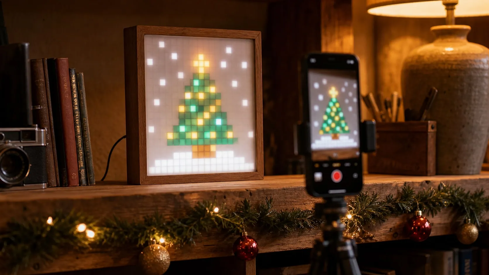
Programmable pixel lights are all over holiday Shorts, Reels and Pinterest boards right now: snow falling across a grid of soft squares, a name scrolling past, a tree drawn in 256 pixels. A finished panel like that is easy to build in a weekend. It’s a flexible LED matrix, a small Wi-Fi board, a frosted front and one plug-in power supply, and with the free WLED firmware it needs no programming at all. It makes a gift that keeps doing something new, and it looks great on camera. Here’s the whole build, step by step, with the parts for each step below.
Step 1: Plan the panel and the power
The panel is a 16 × 16 grid of WS2812B pixels, about 16 cm (6.3 in) square. Each pixel has its own tiny driver chip, so one data wire sets the color of all 256. Three things to settle before buying anything:
- Power budget. Each WS2812B pixel can draw up to roughly 60 mA at full white. 256 of them at full white would ask for over 15 A, more than any small adapter gives. In practice nobody runs a panel like that: behind a diffuser, 30–40 % brightness is already bright, and colored effects use far less than white. The plan is a 5 V, 10 A supply with a firmware current limit set well below it (Step 5).
- One supply for everything. The adapter powers the panel directly and the ESP32 through its 5V pin. The panel’s current never runs through the ESP32 board.
- Firmware or code. WLED is free firmware for ESP32 boards: a web page and phone app with over a hundred effects, presets, timers and a built-in 2D matrix mode. Most builders stop there. If you’d rather write your own animation, the same wiring works with the FastLED library (Step 5).
Step 2: Build the frame and the diffuser
Bare LEDs look like sharp dots. A diffuser a short distance in front of them turns each pixel into a soft square, and that’s the look you see in the videos.
- Print a grid. A 16 × 16 egg-crate grid with 10 mm cells, about 10–15 mm deep, sits between the panel and the front, so each pixel lights only its own square. Printables and MakerWorld have grids made for 16 × 16 WS2812B panels; check the cell pitch matches yours before printing. Print it in black or white PLA: black gives crisp squares, white gives a brighter, softer glow.
- Print or build a frame that holds the panel flat at the back, the grid in the middle and the acrylic at the front, with a slot or hole for the cable at the bottom. A wooden shadow box with the glass swapped for acrylic works too.
- Cut the front. Mark the acrylic with the film still on, score it several times along a metal straightedge with a plastic-cutting knife, and snap it over the edge of the bench. Matte side faces out.
Leave the back open or add a few vent holes. The panel gets warm at high brightness, and the electronics shouldn’t sit in a sealed box.
Step 3: Flash WLED onto the ESP32
- Connect the ESP32 to your computer with a micro-USB cable that carries data.
- In Chrome or Edge, open the official WLED web installer (linked from the WLED project’s site), choose the latest release and click Install. It finds the board’s serial port and flashes it in a minute or two.
- After the restart, the board opens its own Wi-Fi network, WLED-AP. Connect your phone to it (WLED’s default
password is
wled1234), enter your home Wi-Fi details, and the board joins your network. - Install the WLED app on your phone, or open the board’s IP address in a browser. You’ll do the rest of the setup from there once the wiring is done.
If the computer doesn’t see the board at all, try another cable first; then check whether your system needs the driver for the board’s USB-to-serial chip.
Step 4: Solder the power and data wiring
Build it on a breadboard first, test it, then solder it onto a small piece of perfboard that lives at the back of the frame. Besides the parts below you need a 330 Ω resistor, a female 5.5 mm DC jack with screw terminals for the adapter’s plug, and some 18 AWG wire for the power leads.
| From | To |
|---|---|
| DC jack + (5 V) | Panel 5 V power lead, capacitor +, chip pin 14 (VCC), ESP32 5V/VIN |
| DC jack − (GND) | Panel GND power lead, capacitor −, chip pin 7 (GND), ESP32 GND |
| ESP32 GPIO16 | Chip pin 2 (1A) |
| Chip pin 3 (1Y) | 330 Ω resistor → panel DIN (data in) |
| Chip pin 1 (1OE) | GND |
| Chip pins 4, 10, 13 (unused enables) | 5 V |
| Chip pins 5, 9, 12 (unused inputs) | GND |
Wire colors on these panels differ between batches, so go by the labels printed on the board (5V, DIN, GND) and the arrow that shows the data direction. A few details make the difference between a panel that flickers and one that just works:
- Capacitor at the panel. Solder the 1000 µF capacitor across 5 V and GND as close to the panel’s power input as you can. The stripe on the capacitor marks the negative leg.
- Power to the panel’s own power leads. Most 16 × 16 panels have a separate pair of thicker power wires next to the data connector. Feed the 5 V there, not through the thin wire in the data plug.
- Short data wire. Keep the wire from the chip to DIN short; the 330 Ω resistor sits at the panel end.
- Shared ground. Supply, panel, chip and ESP32 grounds all connect. Without that, the data signal has nothing to be measured against.
- Chip in its socket. Solder the empty DIP-14 socket, then press the chip in after the board has cooled, notch matching the socket’s notch.
Before you plug in the panel for the first time, power the board alone and check with a multimeter that you have 5 V, with the right polarity, at the panel’s power leads.
Step 5: Set up the matrix and the brightness limit
In WLED, open Config → LED Preferences:
- Data GPIO: 16. Length: 256. LED type: WS281x. Color order: GRB.
- Current limiter: WLED’s default limit is meant for small USB-powered setups. Set the maximum current to about 5000 mA for a start. That’s half the adapter’s rating and plenty behind the diffuser. Don’t go above 8000 mA.
- Under 2D Configuration, set a 16 × 16 matrix and turn on serpentine, since these panels run back and forth row by row. If an effect looks mirrored or sideways, change the start corner or rotate the panel.
Now try the effects. Snowfall, fire, plasma, rainbow and scrolling text all come built in, and you can save favorites as presets, chain them into a playlist and pick one to start at power-on. Timers can switch the panel on in the evening and off at bedtime.
If you’d rather write the animation yourself, here’s a short snowfall sketch for the Arduino IDE with the FastLED library, using the same wiring:
#include <FastLED.h>

const int DATA_PIN = 16;
const int W = 16, H = 16;
CRGB leds[W * H];

int xy(int x, int y) {                                    // serpentine: every other row runs backwards
  return (y % 2) ? y * W + (W - 1 - x) : y * W + x;
}

void setup() {
  FastLED.addLeds<WS2812B, DATA_PIN, GRB>(leds, W * H);
  FastLED.setMaxPowerInVoltsAndMilliamps(5, 5000);        // never ask the supply for more than 5 A
  FastLED.setBrightness(80);
}

void loop() {
  EVERY_N_MILLISECONDS(120) {
    for (int y = H - 1; y > 0; y--)                       // move every row down by one
      for (int x = 0; x < W; x++) leds[xy(x, y)] = leds[xy(x, y - 1)];
    for (int x = 0; x < W; x++)                           // new flakes in the top row
      leds[xy(x, 0)] = random8() < 20 ? CRGB(180, 200, 255) : CRGB::Black;
  }
  FastLED.show();
}
If the snow falls sideways or upwards, rotate the panel in the frame, or swap x and y in xy().
Step 6: Close it up and film it
Fix the perfboard and the ESP32 to the back of the frame with screws or double-sided foam tape, and give the power cable a strain relief (a cable tie through two holes) so a tug on the cord pulls on the frame, not on the solder joints.
For Shorts and Reels:
- Turn the brightness down. A panel that looks right to the eye often clips to white on a phone camera. Around 20–30 % usually films best.
- Lock exposure and focus on the panel (long-press on most phone cameras), so the picture doesn’t pump as the effect changes.
- Leave some room light on. A totally dark room makes the panel look like a floating rectangle; a lamp in the background shows the frame and the room around it.
- Vertical framing: panel in the upper half, a few ornaments or a garland below it.
Step 7: Make it safe to give
- Test for an evening. Run a bright effect for an hour, then feel the panel, the wires and the adapter. Warm is fine; hot means the current limit is too high.
- Keep the adapter in the open, not behind the frame or under a pillow, and use the panel indoors only.
- Unplug the 5 V supply before connecting USB. After the first flash, WLED updates over Wi-Fi, so the USB port rarely needs to be used again.
- Add a small card for the recipient: “Plug it in, connect your phone to the WLED-AP network, enter your Wi-Fi, then use the WLED app.” That’s all they need to make it theirs.
What it takes in time: an evening of printing for the grid and frame, an hour or two of soldering and wiring, and as long as you like playing with effects. The parts for each step are below.
At a glance
7 picksAs an Amazon Associate I earn from qualifying purchases. If you buy through a link on this page we may earn a small commission, at no extra cost to you. How this works.
BTF-LIGHTING WS2812B 16×16 Flexible LED Matrix
256 individually addressable pixels on one thin, flexible board.
A 16 × 16 matrix is the sweet spot for a desk or shelf panel: big enough for snowfall, a scrolling name or a small pixel-art tree, small enough to run from one plug-in 5 V supply. Each pixel has its own driver chip, so a single data wire from the ESP32 controls all 256 of them.
The flexible board is thin and easy to crease at the corners, so it needs a rigid frame behind it. That frame also holds the diffuser at a small distance, which is what turns 256 sharp dots into soft, even squares of light.
Pro tip Look for the small arrow printed on the board. Data only flows one way, so the controller always connects to the end marked DIN (data in), never to DOUT.
Why we like it
- ✓16 × 16 grid of WS2812B pixels (256 LEDs), each one set to its own color
- ✓Flexible FPCB, so it lies flat in a frame or bends gently around a curve
- ✓Runs on 5 V and works with WLED, FastLED and similar controllers
- ✓JST connectors for chaining several panels into a bigger screen
Keep in mind
- !No controller or power supply included; it does nothing on its own
- !At full white and full brightness it can draw far more current than a typical 5 V supply gives, so brightness has to be capped in software
- LEDs
- 256 × WS2812B (5050 SMD)
- Grid
- 16 × 16
- Size
- about 16 × 16 cm (6.3 × 6.3 in)
- Voltage
- 5 V DC
- Board
- Flexible FPCB
- Use
- Indoor only
- Model
- WS2812B-16x16
ALITOVE 5 V 10 A Power Supply Adapter (50 W)
A closed 5 V, 10 A adapter, so there's no mains wiring to do.
An open-frame industrial supply has more headroom, but it means wiring mains voltage to screw terminals and building a cover for it. For a panel that sits on a shelf or goes to someone as a gift, a closed adapter is the safer shape: the only connection you make is on the 5 V side.
Ten amps covers the panel, the ESP32 and a safety margin, as long as the brightness limit in the firmware stays below what the supply can deliver.
Pro tip Set the controller’s current limit to about 80 % of the supply’s rating (8 A here, or lower), and leave the brick in open air rather than stuffed behind the frame.
Why we like it
- ✓5 V output at up to 10 A (50 W), enough for a 16 × 16 panel with its brightness capped
- ✓Closed adapter with a detachable AC cord, so you never touch mains terminals
- ✓Over-load, over-voltage, over-temperature and short-circuit cut-off, ALITOVE says
- ✓Standard 5.5 mm barrel plug, center positive
Keep in mind
- !The barrel plug needs a matching female jack or screw-terminal adapter to connect to bare wires
- !Listing names CE, FCC and RoHS but no UL or ETL listing
- Input
- 100–240 V AC, 50/60 Hz
- Output
- 5 V DC, 10 A max (50 W)
- Plug
- 5.5 mm outer, 2.1–2.5 mm inner, center positive
- Weight
- 300 g
- Model
- J200-05010000
Lesnlok Translucent White Acrylic Sheet, 8 × 12 in (2-Pack)
Translucent white acrylic that blends the dots into soft squares of light.
Lesnlok sells the same sheet in an opaque white version that lets only a few percent of the light through. For an LED panel you want this translucent one: bright enough to show colors well, cloudy enough to blend the pixels.
A sheet this size cuts into one front panel with plenty left over. Score it several times along a straightedge with a plastic-cutting knife, then snap it over the edge of the bench.
Pro tip Put the matte side toward the viewer. It hides fingerprints and reflections, which matters a lot when the panel ends up on camera.
Why we like it
- ✓Translucent matte white, around 73 % light transmission, Lesnlok says
- ✓Cast acrylic, 1/8 in (3 mm) thick, with protective film on both sides
- ✓8 × 12 in sheet covers a 16 × 16 cm panel with room for a frame edge
- ✓Two sheets, so a cutting mistake isn't the end of the project
Keep in mind
- !Scratches easily once the film is off; keep the film on until assembly
- !Too clear to hide the LEDs if it sits directly on the panel; it needs a small air gap
- Size
- 8 × 12 in (about 20 × 30 cm)
- Thickness
- 1/8 in (3 mm)
- Material
- Cast acrylic
- Finish
- One side matte, one side glossy
- Pieces
- 2
HiLetgo ESP32 Development Board (ESP-WROOM-32)
A Wi-Fi board that runs WLED, with a web page and phone app instead of code.
The classic ESP32 board is the default controller for WS2812B projects, mainly because of WLED: free firmware that gives the panel a web interface, more than a hundred effects, presets, schedules and a phone app. No code is needed to get a working panel.
Its pins run at 3.3 V while the panel expects 5 V data. That’s why this build adds a level shifter between the two.
Pro tip If the computer doesn’t see the board, try a different cable first. Many micro-USB cables from old chargers only carry power, not data.
Why we like it
- ✓ESP-WROOM-32 module with dual-core processor, Wi-Fi and Bluetooth
- ✓Programs from the Arduino IDE, or flashes WLED from a browser
- ✓USB-to-serial chip on board; plug in and upload, no separate programmer
- ✓Pin headers already soldered
Keep in mind
- !Micro-USB, not USB-C, so you may need an older cable that carries data
- !Wide board; on a standard breadboard it leaves only one row of holes free on one side
- Module
- ESP-WROOM-32
- Wireless
- Wi-Fi 2.4 GHz, Bluetooth
- Logic level
- 3.3 V
- USB
- Micro-USB
- Software
- Arduino IDE, ESP-IDF, WLED
Q-MING 60 W Adjustable Soldering Iron Kit (10-in-1)
An adjustable iron with tips, stand and solder for the handful of joints.
This build has only a handful of joints: the power leads, the capacitor and the level-shifter chip’s socket. A simple pencil iron with adjustable heat is enough for that, and the kit covers the small extras a first build needs.
The conical tip suits the chip socket’s pins; a chisel tip heats the thicker power wires faster.
Pro tip Tin both the wire and the pad before you join them, then touch them together with the iron for a second or two. Solder in a ventilated spot and wash your hands afterwards.
Why we like it
- ✓Adjustable temperature, 200–450 °C (392–842 °F)
- ✓Ceramic heater, with an on/off switch on the handle
- ✓Comes with 5 tips, a stand with sponge, 0.6 mm solder wire and flux paste
- ✓Plugs straight into a US outlet, no separate station
Keep in mind
- !Temperature is set with a dial, with no display to show the actual tip temperature
- !Basic stand is light; place it where the cord can't pull it off the bench
- Power
- 60 W, 110 V
- Temperature
- 200–450 °C (392–842 °F)
- Heater
- Ceramic
- Included
- 5 tips, stand, sponge, 0.6 mm solder, flux paste
SN74AHCT125N Quad Buffer with DIP-14 Sockets (5 Sets)
Turns the ESP32's 3.3 V data into the clean 5 V signal the pixels expect.
WS2812B pixels on 5 V expect a data signal close to 5 V. An ESP32 sends 3.3 V, which often works on the bench and then flickers or fails once the panel is in its frame with a longer wire. The AHCT125 reads 3.3 V as a clear “high” and sends out a full 5 V, which removes that guesswork.
It’s a fast one-way buffer, which is what LED data needs. The small two-way level-shifter modules sold for I²C are too slow for WS2812B data.
Pro tip Each buffer has its own enable pin, and it’s active low. Tie the enable for the buffer you use to GND, or the chip will stay silent.
Why we like it
- ✓74AHCT125 is the chip widely recommended for 3.3 V → 5 V LED data
- ✓Four buffers per chip; one drives the panel, the rest stay spare
- ✓DIP-14 package fits a breadboard or perfboard
- ✓Includes a socket for each chip, so the chip never sees the soldering iron
Keep in mind
- !Lesser-known seller with few ratings
- !Bare chips, not a ready-made module; you wire power and the enable pin yourself
- Chip
- SN74AHCT125N
- Function
- Quad buffer, three-state outputs
- Package
- DIP-14
- Included
- 5 chips, 5 sockets
BOJACK Electrolytic Capacitor Assortment (24 Values, 630 pcs)
Includes the 1000 µF capacitor that sits across the panel's power input.
When a WS2812B panel switches from dark to bright, the current jumps in a fraction of a second. A large capacitor right at the panel’s power input covers those jumps, and it also softens the spike when the supply is plugged in with the panel already connected.
The assortment makes sense if you plan more than one build. The smaller values cover decoupling, timers and repairs.
Pro tip Electrolytic capacitors have a polarity: the stripe marks the negative leg. Fit it the wrong way round on 5 V and it can bulge or burst, so check the stripe before you power up.
Why we like it
- ✓24 values from 0.1 µF to 1000 µF, 630 pieces in a labeled box
- ✓Includes 1000 µF / 16 V, the usual size across a WS2812B panel's power input
- ✓Rated -40 to +105 °C, ±20 % tolerance, BOJACK says
- ✓Through-hole leads, easy to solder by hand
Keep in mind
- !Only ten of the 1000 µF capacitors; the box is mostly smaller values
- !More than you need if you build just one panel
- Values
- 24 (0.1–1000 µF)
- Pieces
- 630
- Voltage ratings
- 10, 16, 25 and 50 V
- Temperature
- -40 to +105 °C
- Model
- BJ-CPT24-630